
Project
Background
Purpose
This project was a part of Cal Poly Pomona's BANSHEE UAV. BANSHEE UAV is an academic multidisciplinary project that involves Aerospace Engineering and Electrical Engineering. The focus of the project is to create a system in which a UAV drone can extend its flight time without having to come back to the origin point for a battery swap. Currently, the popular choice to power a UAV drone is a LiPo battery. The main issue with using a LiPo battery is that the usable power of the LiPo battery is very minimal. In terms of flight time, it can only last around 20 to 30 minutes before needing to safely descend and land. Therefore, the solution purpose by this project was to create a base station where a drone can autonomously land by using computer vision and have its battery autonomously hot-swapped in seconds.
Role
For this project, I was responsible for creating a Wireless Power Transfer system that can wirelessly send power to a UAV drone while its battery is being replaced at the base station. The purpose of keeping the drone powered on while the battery is being hot-swapped is because the drone's memory, which includes the flight path, will be erased if it is completely powered off.
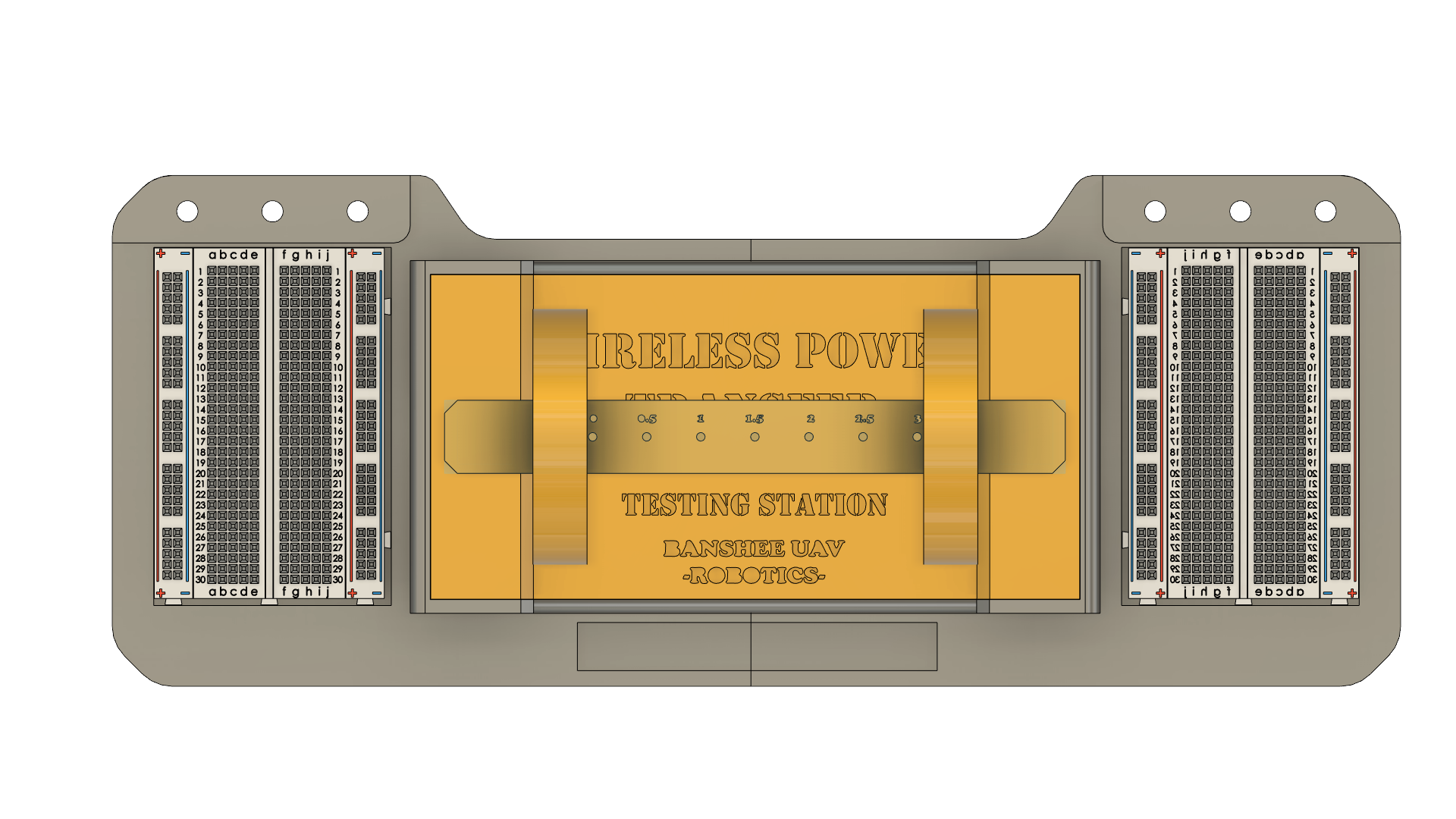
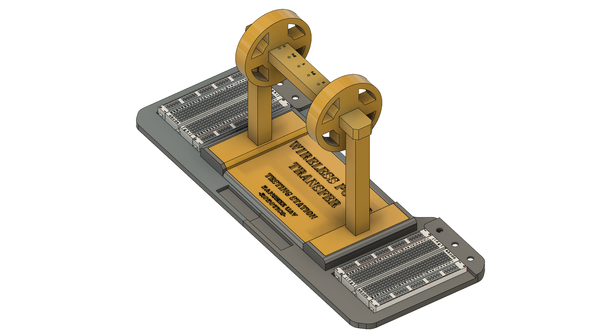
3D CAD Modeling
of the Test Station
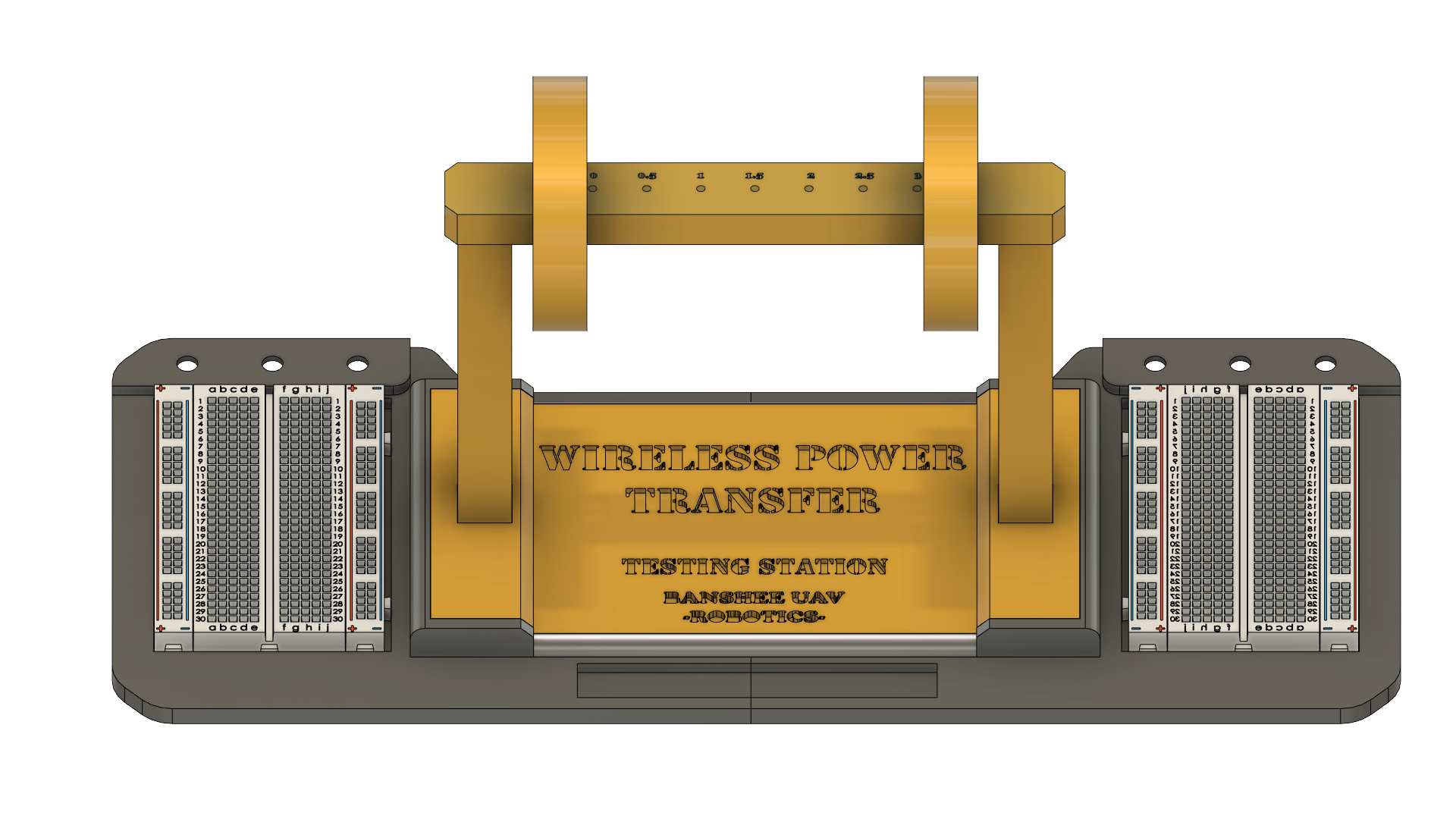

LEFT
RIGHT
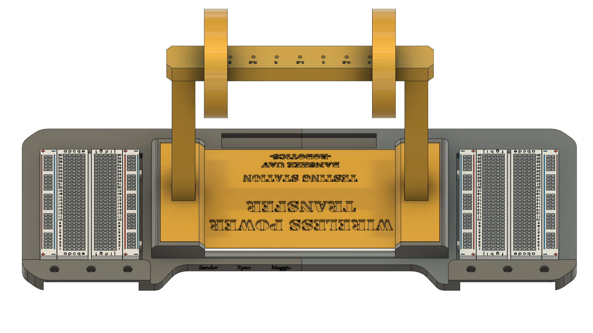
BACK
Circuit Schematic and Block model
Purpose
The circuit consists of 4 different systems working as a whole. There is an inverter circuit, induction coils, a rectifier circuit, and a LED that acts as a load.
By looking at the block model, the DC input goes into the inverter circuit. The inverter circuit is responsible for converting the received DC voltage into AC voltage. The converted AC voltage will then pass through two wireless induction coils. The induction coils are responsible for transferring voltage from one circuit to the other circuit. Once the AC voltage is transferred, it will go into the rectifier circuit. The rectifier circuit is responsible for converting the AC voltage to DC voltage. Once the voltage is converted, it can be used for any DC load. In this case, for testing purposes, it will be used to light an LED.

Circuit Block Model

Circuit Schematic
Inverter Circuit
(DC to AC)
Purpose
The inverter circuit that is being used is known as the Wien Bridge circuit. For wireless power transfer to be possible, an AC voltage with a resonant frequency is needed. In this case, the Wien Bridge circuit is able to take a DC input and produce a sinusoidal waveform at the output.
Components
The circuit consists of 5 resistors, 1 OP amp, 2 switching diodes, and 2 capacitors.
Resistors R1 and R2 are a part of the negative feedback loop and will be used to begin the oscillation waveform.
Resistor R5 and the Diodes D1 and D2 are used as a diode clamp. This will be used for amplitude stabilization to minimize distortion.
Resistor R3 and R4 and Capacitor C1 and C2 are a part of the positive feedback loop. These components are used to select the desired resonant frequency for the sinusoidal waveform.
Since the Wien bridge circuit is based on an OP amp, the OP amp chosen will need to be a high-speed OP amp that can generate oscillations at frequencies greater than 100kHz.

Wien Bridge (Inverter Circuit)
Induction Coils
(Wireless Power Transfer)
Purpose
The induction coils are the circuit components that will transfer power from the inverter circuit to the rectifier circuit.
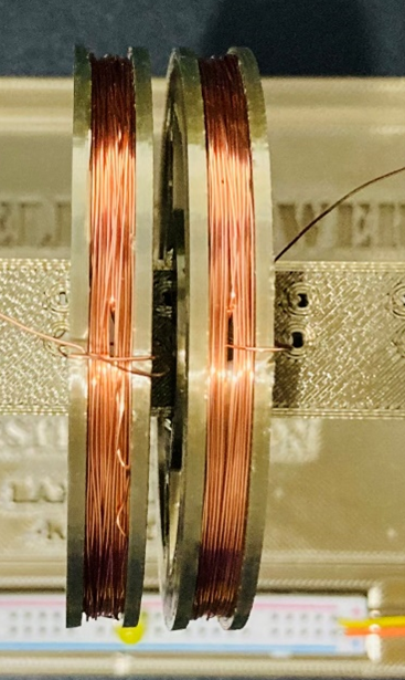
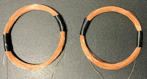
Inductive coils
There are two induction coils. There is a transmitting (Tx) coil and a receiving (Rx) coil. The Tx coil is connected to the inverter circuit, while the Rx coil is connected to the rectifier circuit. The idea is that the two inductive coils in an inductive coupling system act as a transformer with an air gap. As a result, this will allow for the flow of electrical energy to transfer from one coil to another at the same frequency.
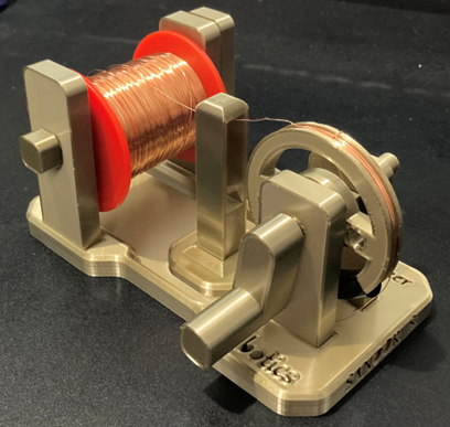
3D-Printed Components
The inductive coils are custom-made, meaning that the number of windings/turns is mathematically determined by a formula. Depending on the inductive values of the coils that are needed, a 3D-printed coil maker was produced to aid in the process of creating the inductive coils.
The coil maker features a holder for the copper wire to be placed and a coil holder for the wire to attach to. If 25 turns are determined for the coil, then the handle on the coil maker will be turned 25 times to create the inductive coil.


Rectifier Circuit
(AC to DC)
Purpose
The rectifier circuit is responsible for converting the received AC voltage into DC voltage. The circuit that is used is a Full Wave Rectifier Circuit with a Smoothing Capacitor.
Components
The circuit consists of 4 diodes. The 4 diodes are responsible for using the outputs of the two half-wave rectifiers to produce a full-wave rectification signal.
By placing a large capacitor in parallel with the load, it will be able to generate an output voltage with small ripples that is essentially DC voltage.
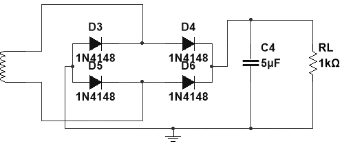
Full Wave Rectifier Circuit with a Smoothing Capacitor
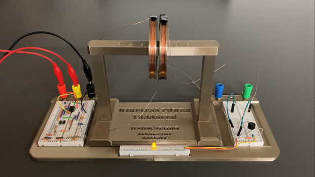
Full Build Testing Station
Purpose
The testing station was used for the purpose of testing the wireless power transfer from one inductive coil to another.
Features
The testing station features two small breadboards on the left and right sides. On the left side, the breadboard holds the inverter circuit. On the right side, it holds the rectifier circuit.
In the middle, the small breadboard is used to place an LED. The LED will light up as the two inductive coils are moved near each other to produce inductive coupling and transfer energy.
Also, in the middle section, there is a stand where two inductive coil holders are placed. This aid in the process of moving the coils together to induce the wireless power transfer.
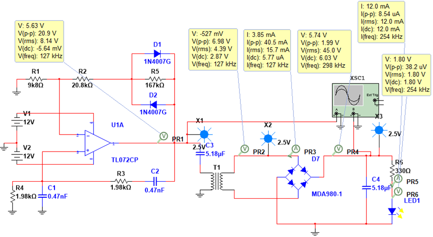
Circuit Analysis using NI Multisim
Purpose
Circuit analysis needed to be performed in Multisim in order to check that the system was working correctly before testing it in the lab.
Circuit Analysis Schematic
From the circuit schematic, the frequency measured at the output of the inverter circuit is 127kHz. The frequency measured at the output of the Rx inductive coil, once the voltage was transferred, was 127kHz. Since the resonant frequencies are the same, this proves that the original signal was able to transfer from one coil to the other.
After the received AC voltage passes through the rectifier circuit, it is converted to DC. The schematic shows that the measured DC voltage was 6.03V. Furthermore, this DC voltage was used to light up the yellow LED as shown in the schematic.
Oscilloscope
The oscilloscope figure is capturing the signal coming out of the inverter circuit. This demonstrates that the inverter circuit is capable of producing an oscillation waveform.
Circuit Analysis using NI Multisim
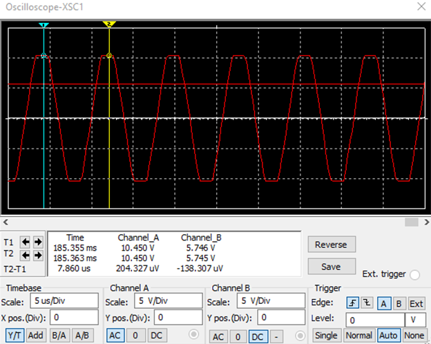
Oscillation waveform captured from the output of the inverter circuit
Demo Videos
Purpose
There are two demo videos to demonstrate the wireless power transfer system in action.
Videos
The first video shows the yellow LED being turned on as the two inductive coils are moved closer to each other. Also, it shows the LED turning off as one inductive coil moves away from the other.
The second video shows the signal of the Rx inductive coil being captured on the oscilloscope as the Rx coil moves closer to the Tx coil to produce wireless power transfer.
Inductive coils producing wireless power transfer
Capturing the signal of the wireless power transfer on the Oscilloscope