Project
Background
Purpose
This project came to fruition for the purpose of further exploring and developing my recently acquired skills in 3D CAD modeling. As the 3D model for the rover progressed, I saw the potential of adding electronics in order to make the rover controllable and moveable. As the possibility of creating a physical rover became real, I began adding components to the 3D model that were widely available for purchase, such as servo motors, DC motors, bearings, metal rods, and shaft locking collars.
3D Printing
3D printing took approximately 1 month and 2 weeks of nonstop printing to complete. All the printing was performed by a single Creality Ender 3 V2. Approximately 2.5 rolls of PLA filament were used.
Components
As for the physical components, such as bearings, screws, shaft locking collars, and servo motors, the exact 3D models were downloaded and sourced from either the official company's website or from Grabcad. This ensures that fitment will not be an issue when the physical building process begins.
Motors
For the motors, two separate motors were chosen for the purpose of steering and wheel movement. For steering, LewanSoul LX-16A Full Metal 17 kg High Torque servo motors were chosen. The steering does not need to be fully continuous. Therefore, the LX-16A servo motor, which is limited to 0 to 240 degrees, will be sufficient. Also, the provided 17 kg of high torque will provide a significant amount of force to move the wheels as the weight of the Rover will be acting on the wheels. For the wheel movement, 200 RPM 12V DC motors were chosen. Also, L298N motor drivers were paired with the 12V DC motors.
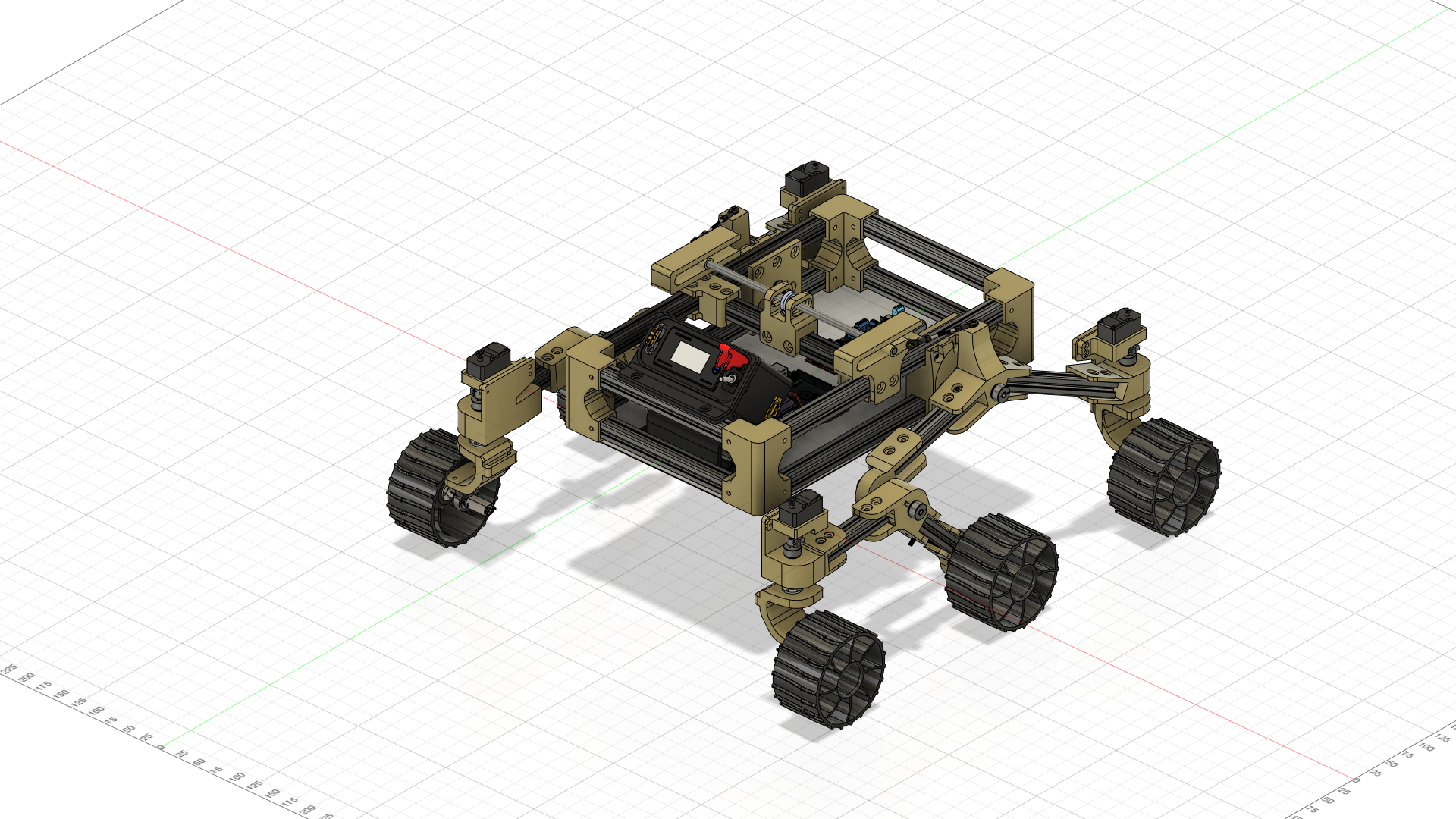
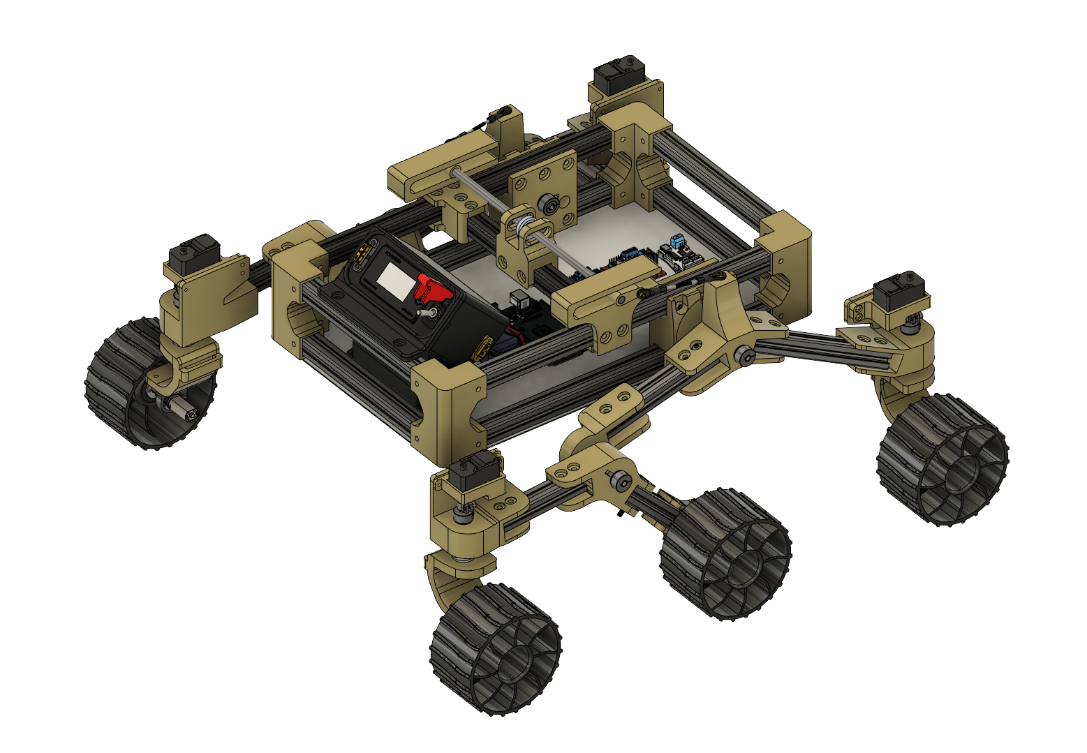
3D CAD MODELING
IN AUTODESK FUSION 360
IN AUTODESK FUSION 360
BACK
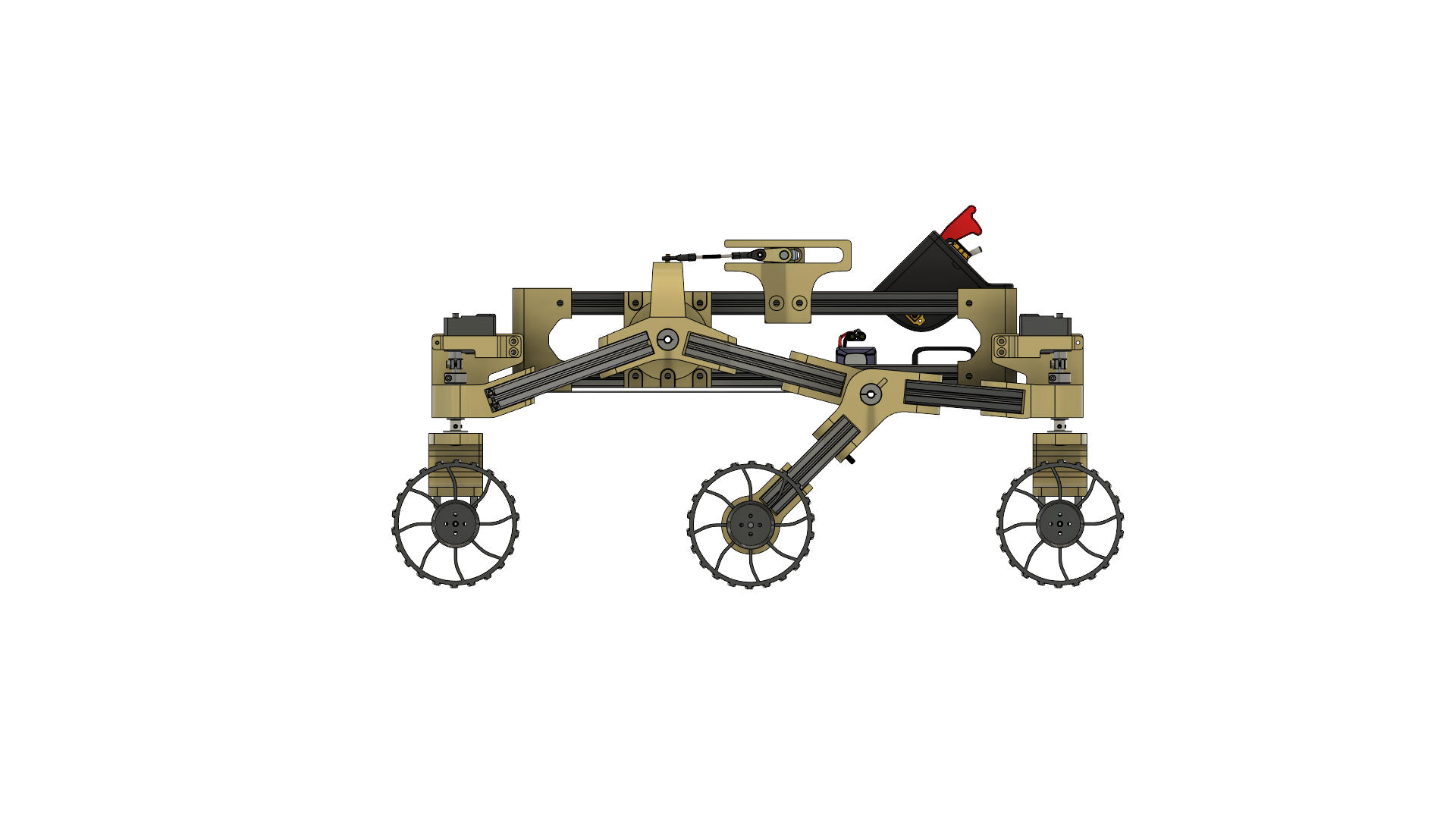
LEFT
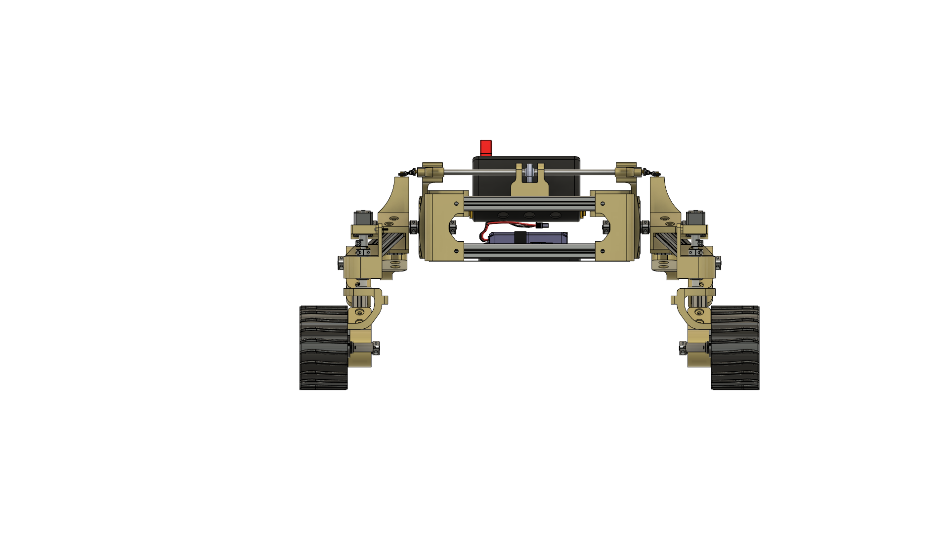
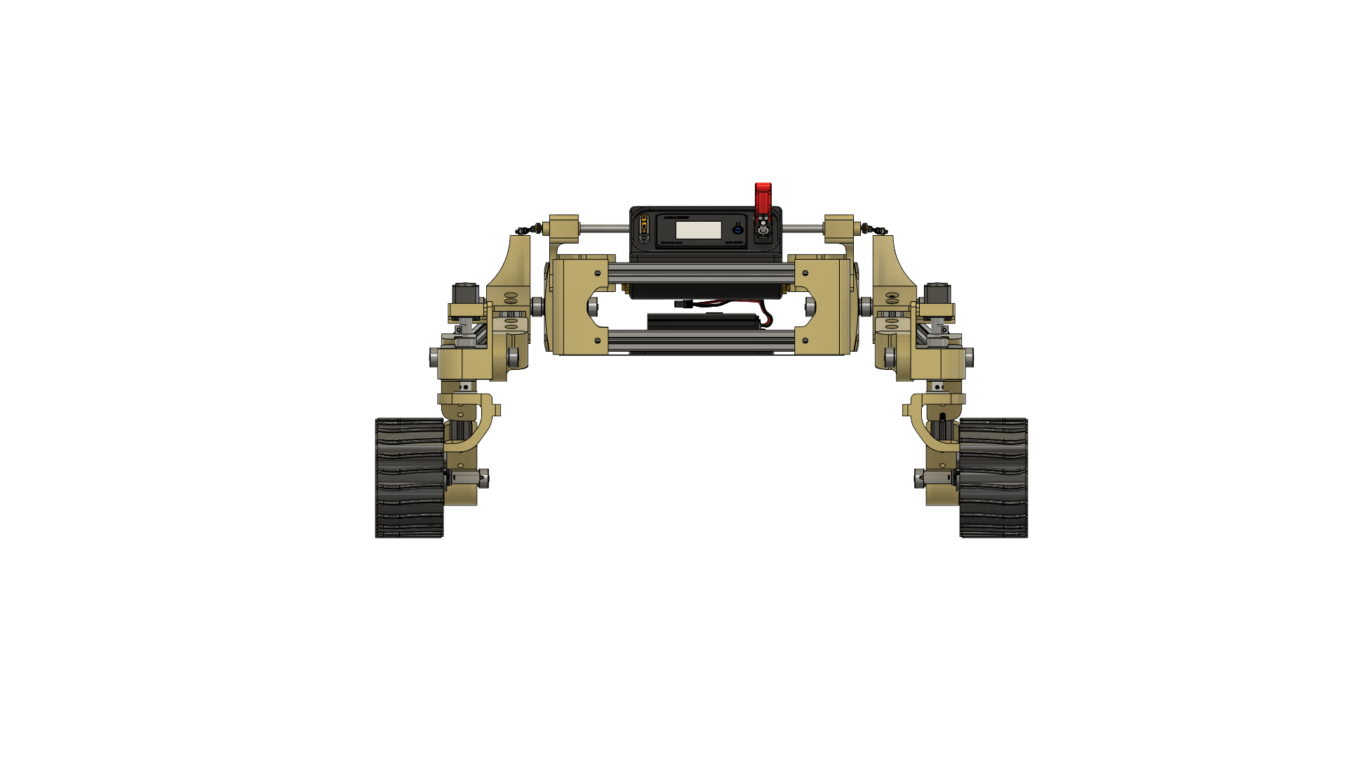
FRONT

RIGHT
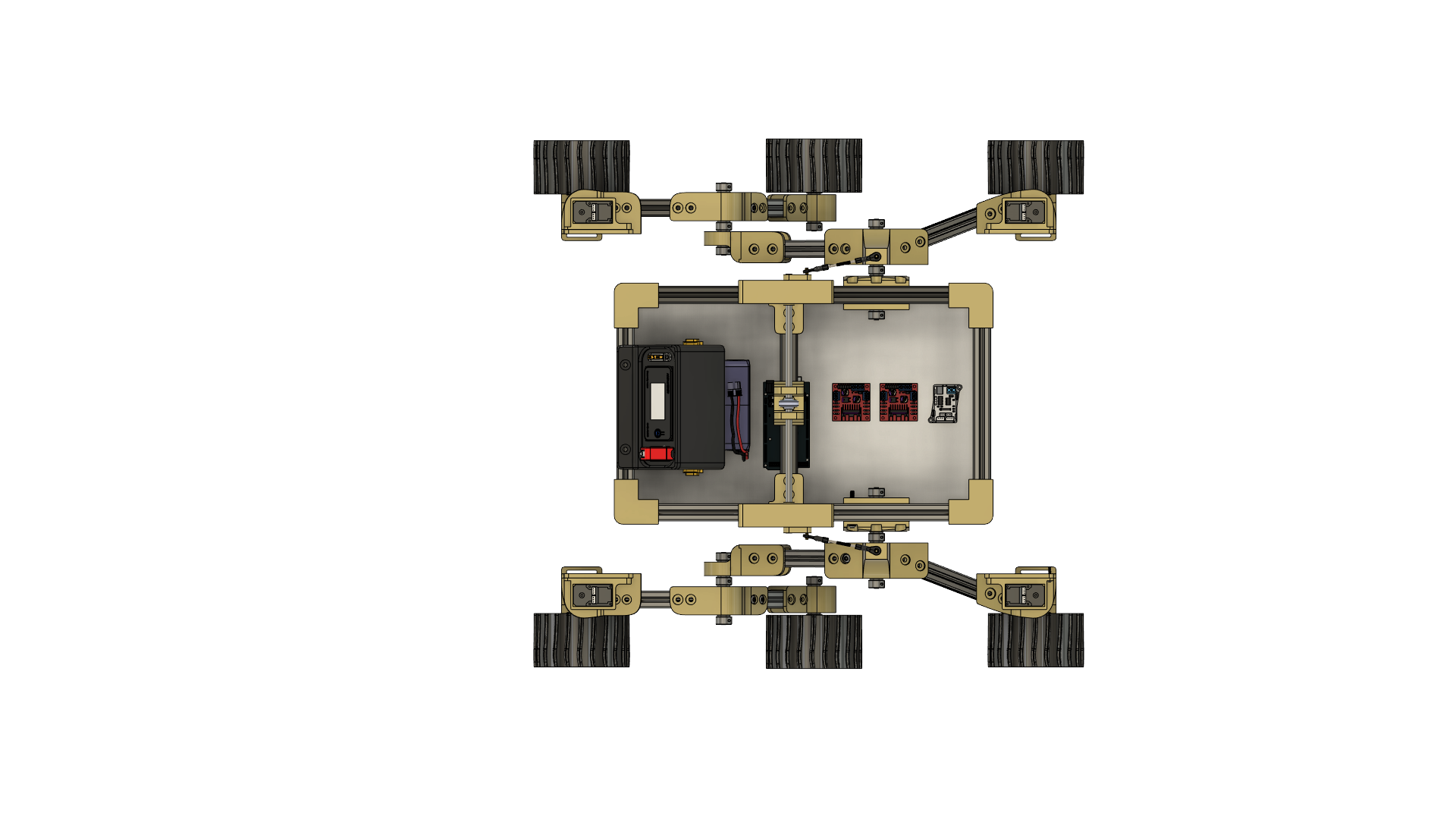
TOP

BOTTOM
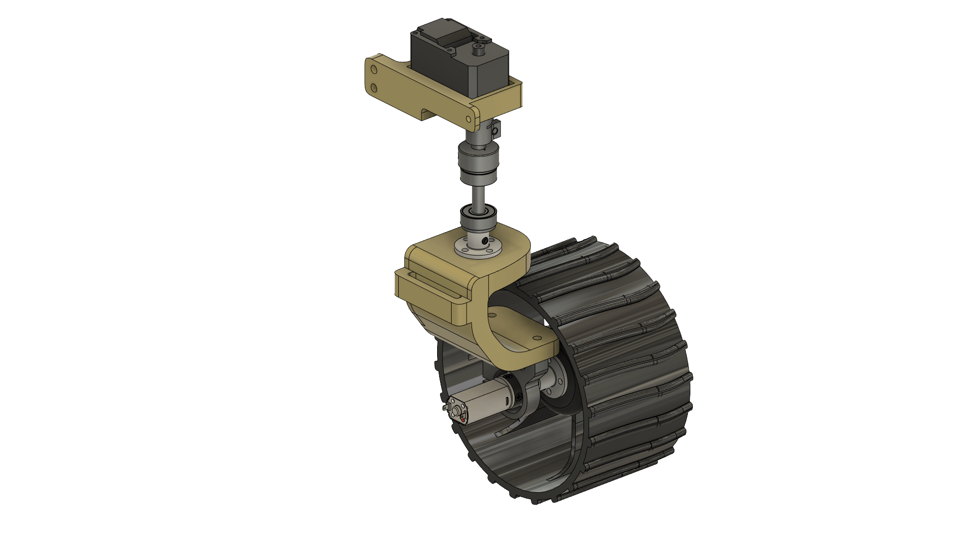
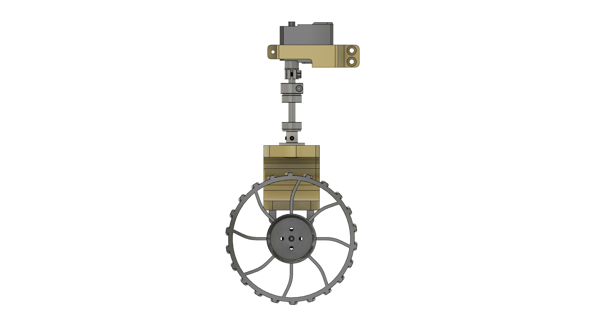
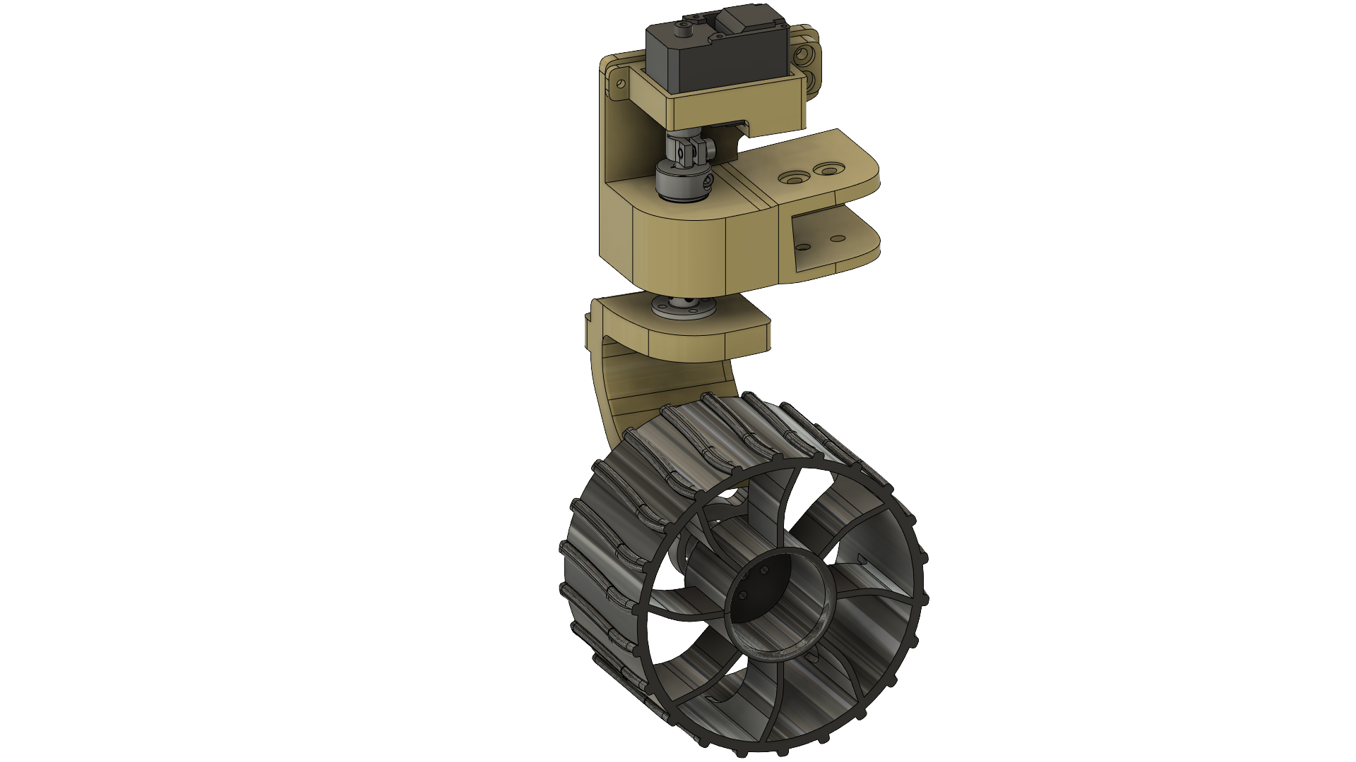
Wheel and Motor Structure
Steering
The motor mounted on the top is responsible for steering. There are four LewanSoul LX-16A Full Metal 17 kg High Torque servo motors at each corner of the rover. The servo motor uses a Clamping Servo to Shaft Coupler (25 Tooth Spline to 6mm Round Bore) to connect to a metal rod (6mm bore). At the end of the metal rod, it is connected to a flange coupling connector, which is mounted to a 3D printed wheel mount.
ACCELERATION
The motor mounted on the wheel is responsible for accelerating forwards and backward. There are four 12V DC motors at each corner of the rover. The 3D printed wheel mount has connected to it a 1400 Series 1-Side, 2-Post Clamping Mount (21mm Bore). In turn, the clamping mount is used to mount a 12V DC motor which is connected to a 3D-printed wheel.

OVERVIEW 1

SIDE 1
OVERVIEW 2

BACK
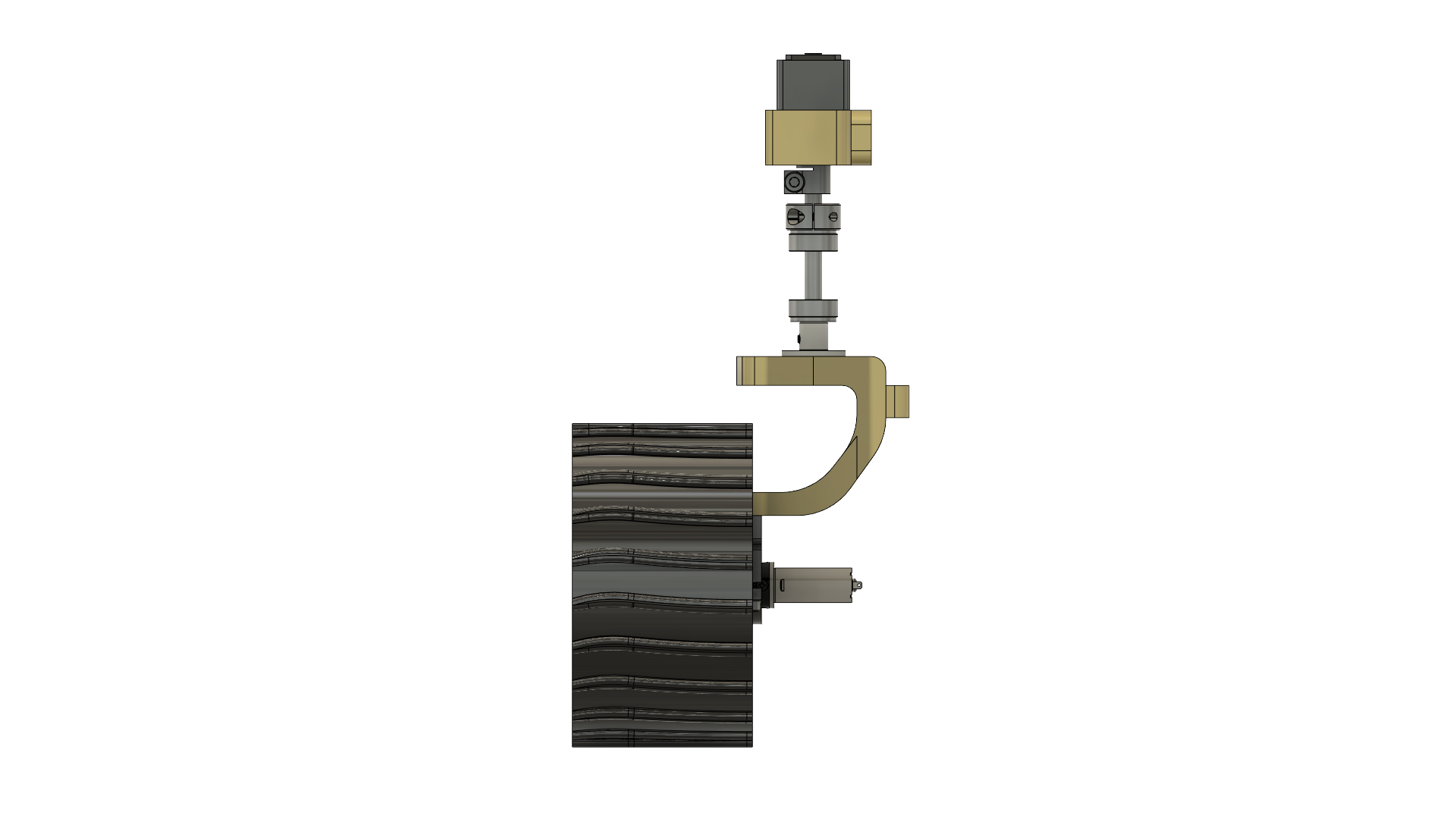
SIDE 2
FRONT
OVERVIEW 1 - ALL COMPONENTS

OVERVIEW 2 - ALL COMPONENTS
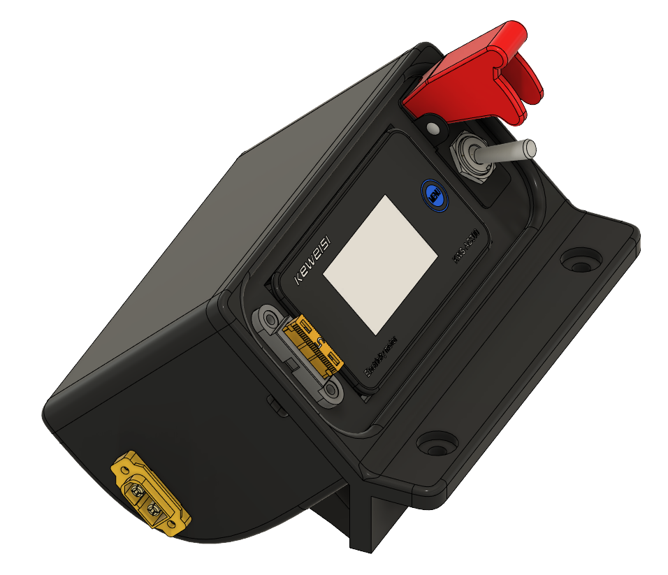
Power Box
PURPOSE
The customized 3D-Printed Power Box will be used to distribute power to the Rover's electrical components, such as the L298N motor driver, the servo motor bus, and an Arduino Mega 2560. On the right side, there is an XT60E-Male connector, to which a power source will connect too. In this case, a 2s 7.4V 5200mAh 50C LiPo battery will be used as the power source. On the left side, there is another XT60E-Male connector. This will be used as the power output connection. The main power wiring harness will connect to this plug.
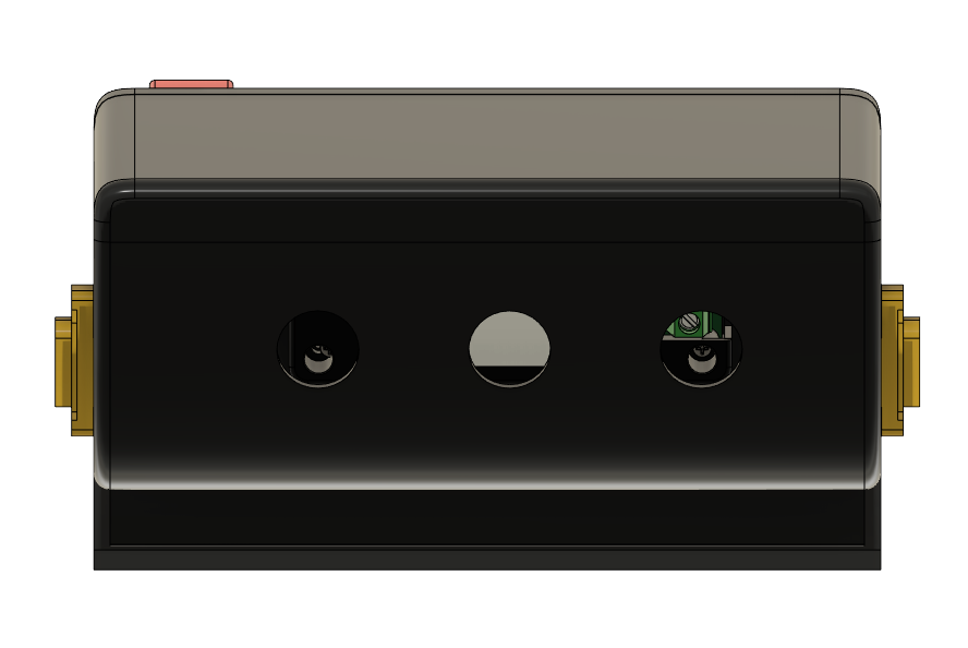
Features
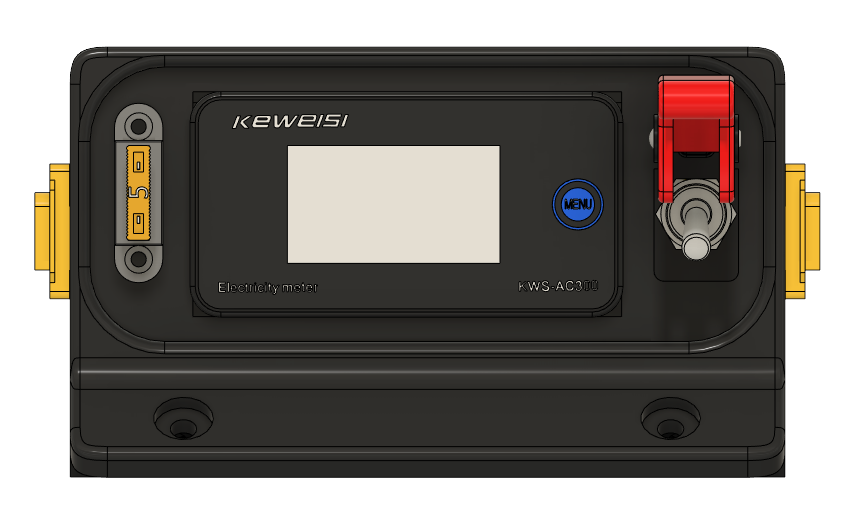
The front of the Power Box features a heavy-duty on/off switch with red LED indication light, a DC meter monitoring screen, and a fuse. The heavy-duty on/off switch will safely turn the Rover on and off, as opposed to merely plugging/unplugging the battery. The DC meter monitoring screen will provide feedback, such as voltage, current, and power, of the entire circuit as the Rover is operating. The mountable ATC fuse will ensure that the fuse will blow to create an open circuit and stop power to the main wiring harness if the current exceeds the fuse limitation. This will provide added protection in the case that excess current is drawn from malfunctioning/stalling motors.
LEFT
BACK

RIGHT
FRONT
videos
Building the Power Box
Showcasing the Power Box
Turning on the Power Box and changing the voltage on the DC meter display
Circuit Schematic
Power Box
The circuit schematic is the road map for connecting the electronics. Beginning from the left, the 7.4v 2s LiPo battery is connected to a switch. The switch leads to a 15A fuse. After the fuse, it is connected to a DC voltage meter. At this point, all the mentioned components are contained inside the customized Power Box.
Main Power Wiring Harness
Coming out of the power box, there is an XT60 male connector, which can be seen on the schematic as XT60_MAIN. At the end of this XT60 connector, it can be seen that there is a circuit connected to four XT60 connectors (XT60_1, XT60_2, XT60_3, & XT60_4). This is known as the main power wiring harness and will be created solely for this project.
Component Connections
Connected to the main power wiring harness are an Arduino Mega 2560, two L298N motor drivers, and a LewanSoul Bus Linker.

Circuit Schematic
main power wiring harness
Purpose
The main power wiring harness connects to the XT60-male connector on the left side of the Power Box. This specific XT60-male connector is the power output plug. The main power wiring harness is used to distribute power to any electronics connected to it. In this case, an Arduino Mega 2560 Rev3, two L298N motor drivers, and a LewanSoul Bus Linker.
Build
The main power wiring harness has a main connector that is used to connect to the Power Box to receive power. Following the main connector, there exist four XT60-male connectors that are used as inputs. These four connectors are running in a parallel configuration with the main connector. In this case, the voltage will be the same across each device, but the current received will be different for each device. This is needed as each electronic will require different current specifications to run properly.

Main Power Wiring Harness
Soldering the XT60 connectors to each wire
Adding electrical tape and wiring loom to protect the wiring harness
Controller
Purpose
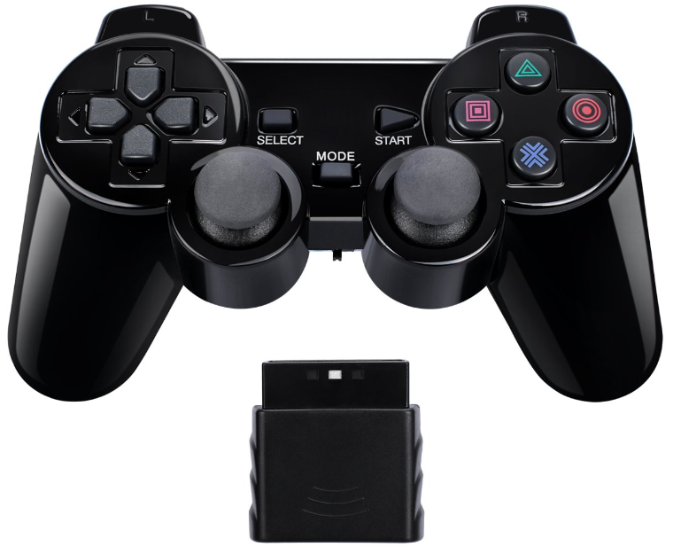
The controller used to steer and accelerate the rover is a PS2 Bluetooth controller bought on Amazon. For this project, this particular controller meets the needs, as the only function that is needed is to steer and accelerate. Furthermore, the controller's Bluetooth capability has been proven to work great. Notably, hobbyists have already successfully used it in numerous Arduino-based projects to provide controls.
Software
Purpose
Since an Arduino Mega 2560 Rev 3 was being used, the code was written in Arduino IDE. The code provided functionality for steering and accelerating.
Steering Programming
The code for steering is written specifically to control the LewanSoul servo motors. The steering capability was configured to run two methods.
The first method will only move/steer the front two wheels, while the back two wheels remain straight. This method is similar to how a car steers.
The second method will move/steer the front two wheels and the back two wheels. If steering right, then the front two wheels will point towards the right, and the back two wheels will point towards the left. If steering left, then the front two wheels will point towards the left, and the back two wheels will point towards the right. Regardless if one wants to move left or right, this method will produce a spinning effect while remaining in place. This will allow the Rover to turn without moving forward. This feature is great for navigating in tight spaces.
Acceleration Programming
The code for acceleration is written specifically to control the 12V DC motor, which is paired with an L298N motor driver. The code provides a way to control the acceleration of the 12V DC motor. The motor is capable of moving up to 200 RPM. However, the code will allow the user to control the RPM speed. Therefore, the acceleration will be a variable speed. The user will be able to crawl at a low speed or accelerate at top speed at any given moment.
Remote control Programming
The PS2 controller connects to the Arduino via a Bluetooth dongle. Hence, the setup code was written so that the Arduino would recognize the Bluetooth dongle and connect to the PS2 controller. More code is written so that specific buttons and button combinations will perform specific steering methods and variable acceleration.
Component List
The project features the following components:
Aluminum Extrusion 20x20 (Cut to various sizes)
Drop-in Tee nut (5mm) (100 pc)
606-2RS Bearings (6mm) (20 pc)
Turn Buckle (2pc)
Shaft Locking Collar (6mm) (4pc)
Flange Coupling Connector (6mm) (4pc)
Flange Coupling Connector (4mm) (4pc)
12v DC Motor (4pc)
Motor Driver for 12DC Motor
LewanSoul LX-16A Full Metal 17kg High Torque (5pc kit)
M5 screws (10mm in length)
Metal Rod (6mm bore)
Metal Rod (8mm bore)
Clamping Servo to Shaft Coupler (25 Tooth Spline to 6mm Round Bore)
1400 Series 1-Side, 2-Post Clamping Mount (21mm Bore)
Rod End Bearing (8mm Bore)
12V 20A Rocker Switch
DC Meter
Fuse holder mount
XT-60 connector
Arduino Mega 2560 Rev3
24 AWG wire
Fuse kit
Dupont connector kit
XT60-E Male panel mount