
Project
Background
Purpose
The 3-Axis Robotic Arm project served as my introduction to robotics. I choose to build this robotic arm while I was in grad school and pursuing a Master's in Electrical Engineering while focusing on Robotics for my Master's Project. Aside from working on my Master's project, I wanted to further explore the field of Robotics. Beginning this project helped me understand more about kinematics, payload, and end effectors. Also, by creating this robotic arm from scratch, I learned plenty about how the mechanical side of things works. For instance, I learned that not all motors are capable of producing the desired torque to pick up a heavy payload. Therefore, I had to integrate belts and pulleys to produce more torque to use the same motor to pick up the payload. This project was definitely a great introduction to 2D & 3D CAD, 3D printing, robotics, and motors.
Furthermore, this project was the first time I had done 3D CAD modeling as well as 3D printing. Therefore, more simple techniques were used to create the model.
3D Printing
3D printing took approximately 59.32 hours (2.47 days) of nonstop printing to complete. All the printing was performed by a single Creality Ender 3 V2.
Components
The components used in the 3D model, such as pulleys or flange couplers, were created manually and not downloaded from Grab Cad or any official parts website. As stated earlier, this project was my introduction to 3D CAD modeling. As I gain experience, future projects included the official part model. However, for this project, I manually measured each part with a caliper and sketched the corresponding dimensions.
Motors
The robotic arm features three stepper motors. There are two short-body NEMA 17 stepper motors. One is attached to the bicep and the other one is attached to the shoulder. These short-body motors are used for vertical movement. A normal NEMA 17 stepper motor is attached to the base to create 360 degrees of horizontal movement. Stepper motors were chosen because of the known precision they can produce. For example, 3D printers use stepper motors because they need very precise movements in order to print with great detail. Although great at precision, stepper motors are not known to produce a lot of torque. Therefore, they cannot be considered for carrying heavy payloads.
For this project, I chose to use stepper motors for their precision characteristics. To combat the problem of low torque, I used belts and pulleys to produce added torque for each stepper motor.
3D CAD MODELING
IN AUTODESK FUSION 360
IN AUTODESK FUSION 360
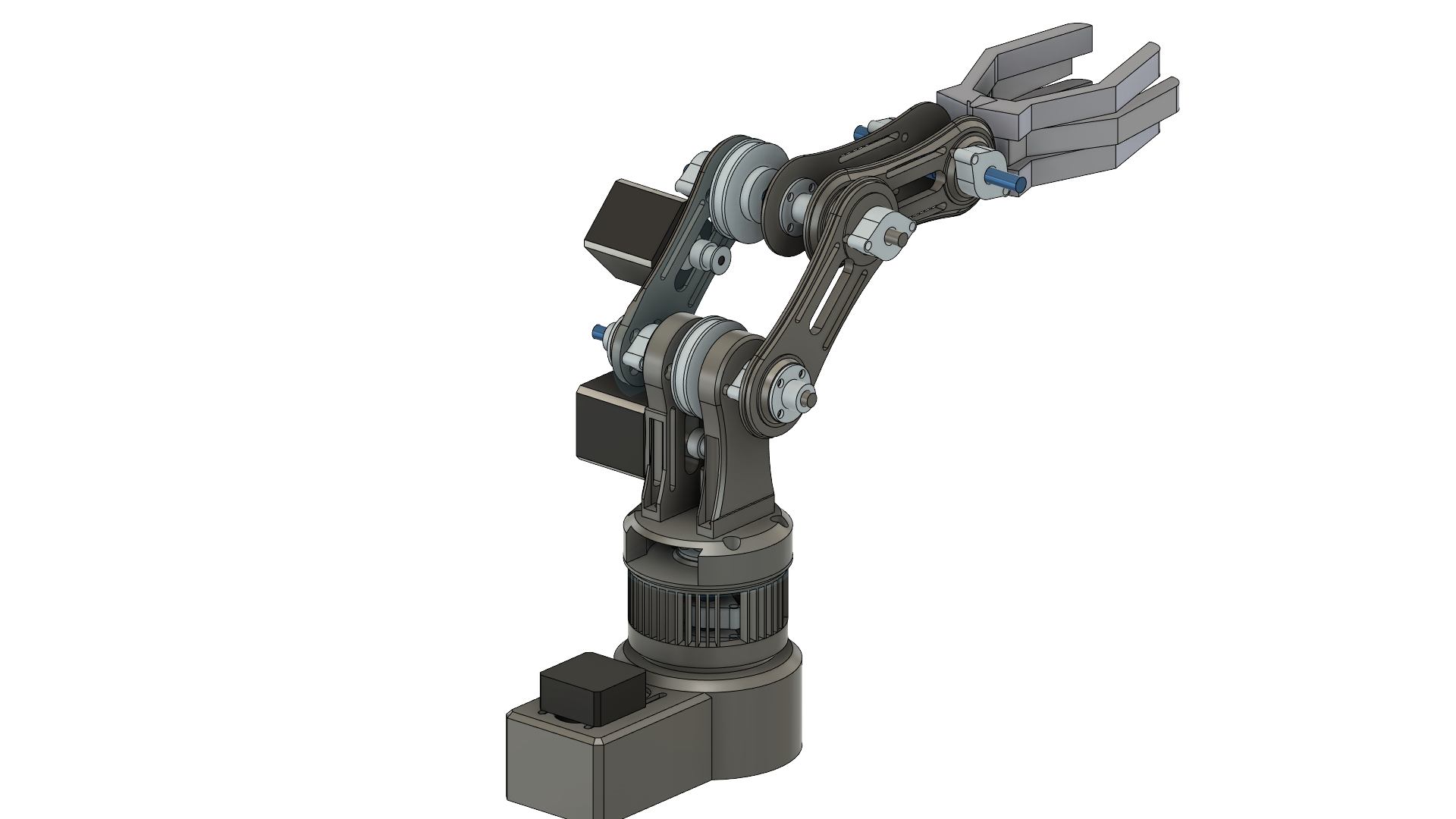
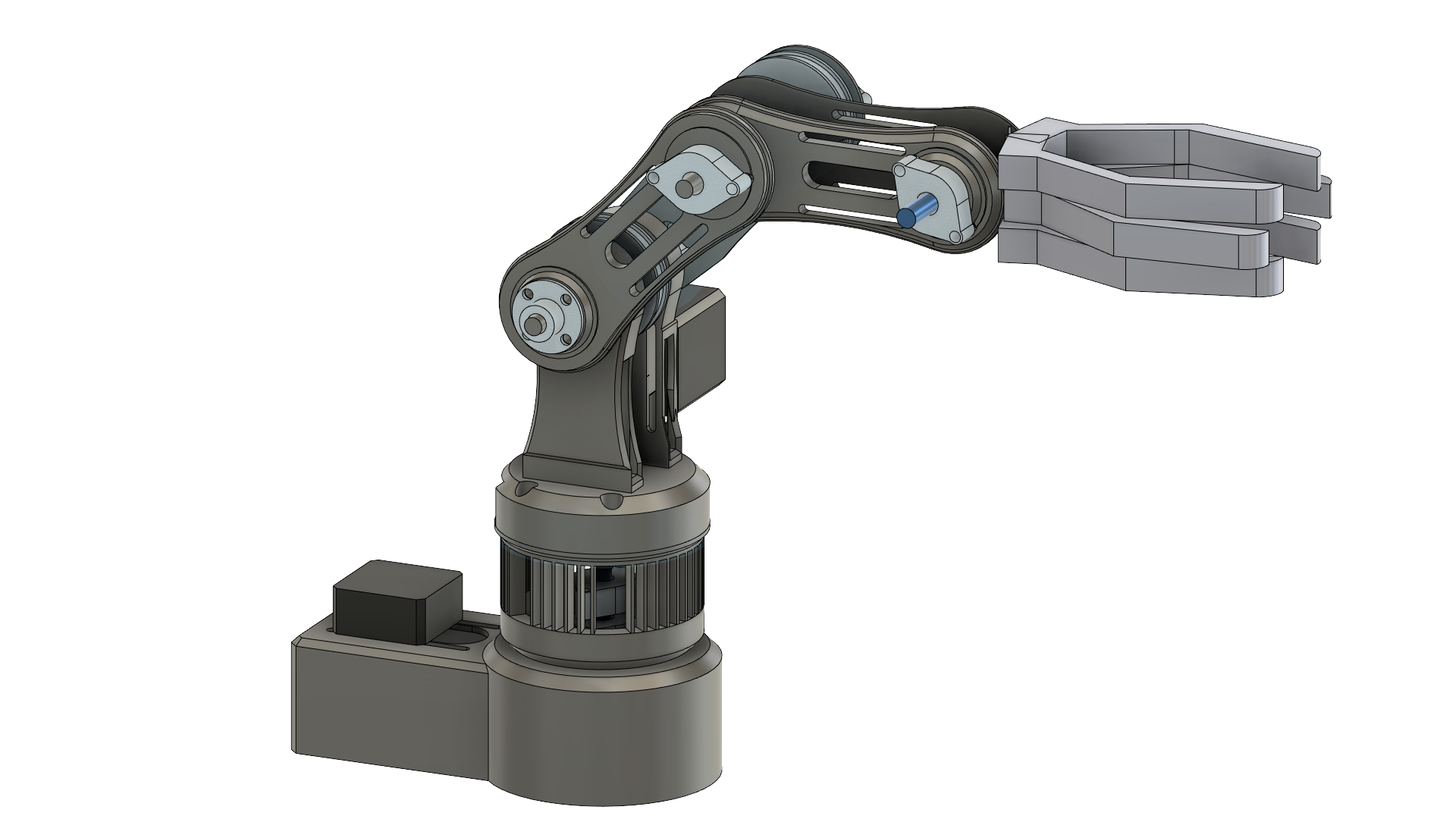
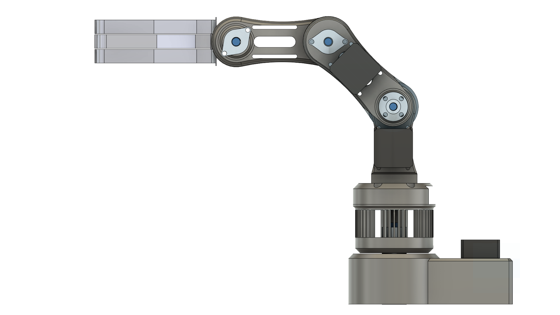
Overview
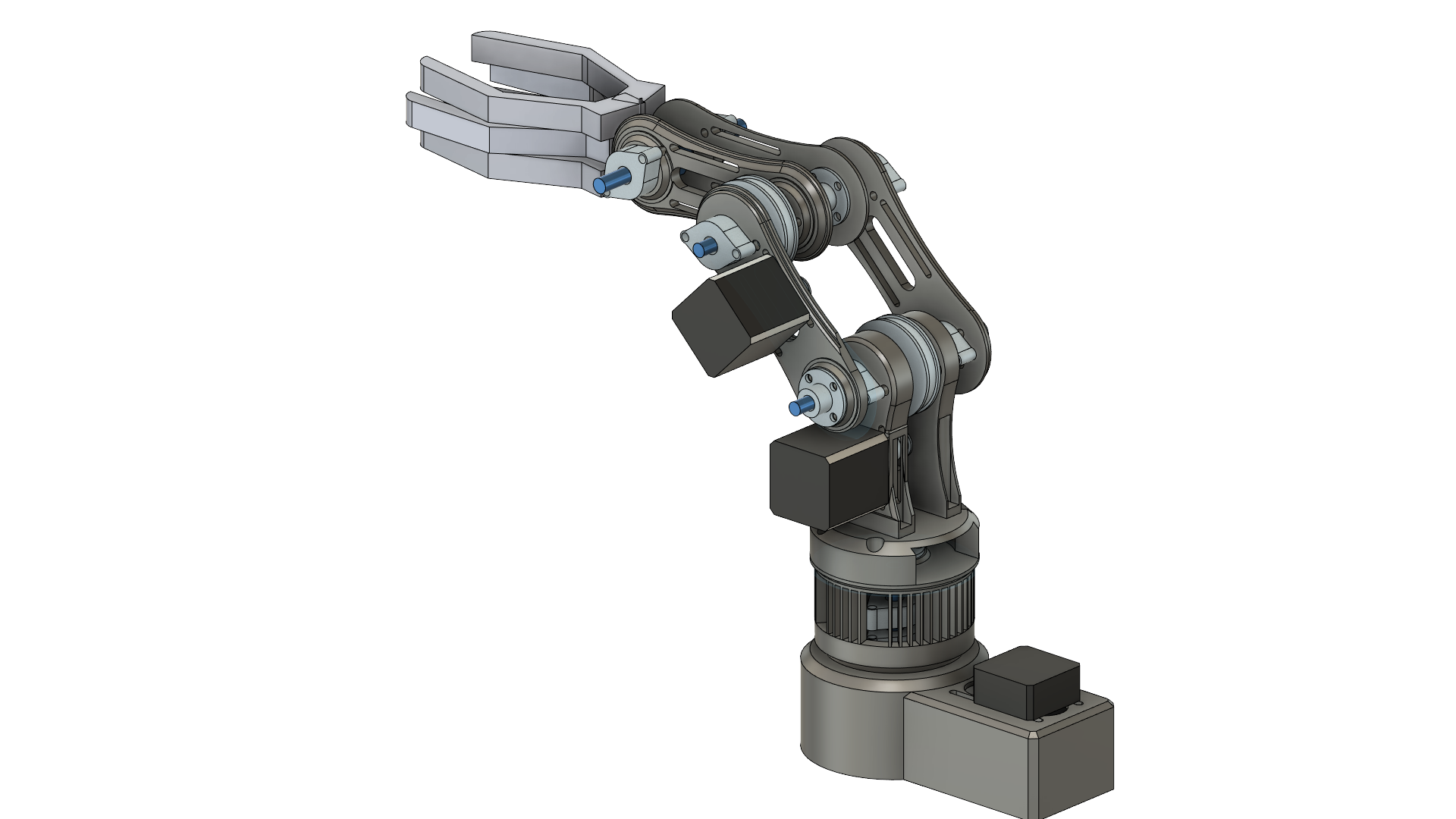

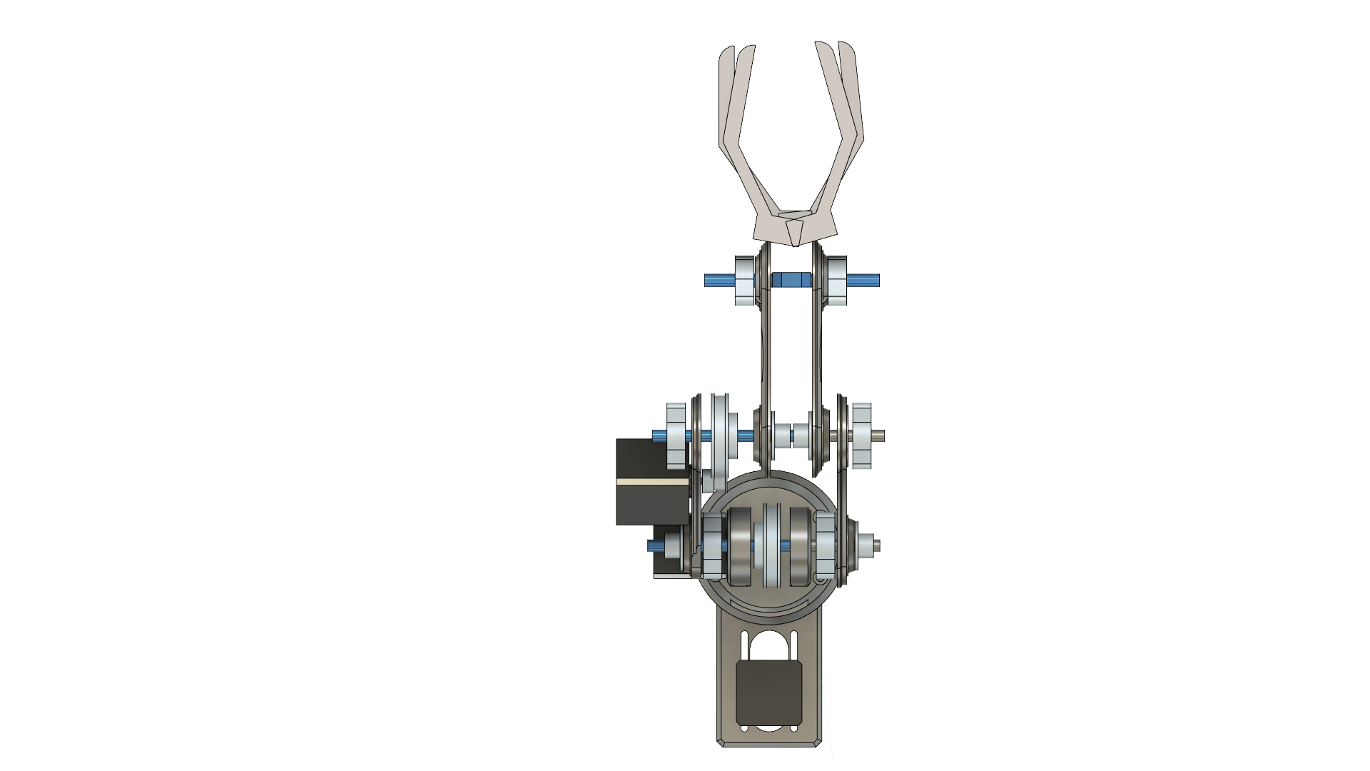
RIGHT
RIGHT
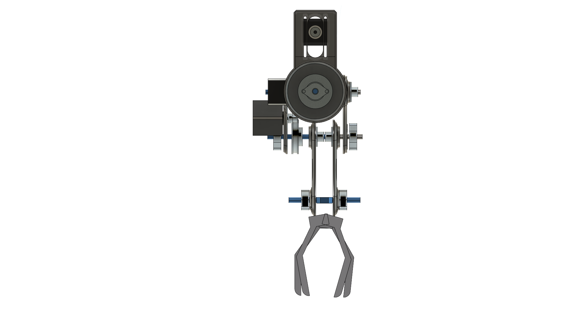
Side View
LEFT

RIGHT
TOP
BOTTOM
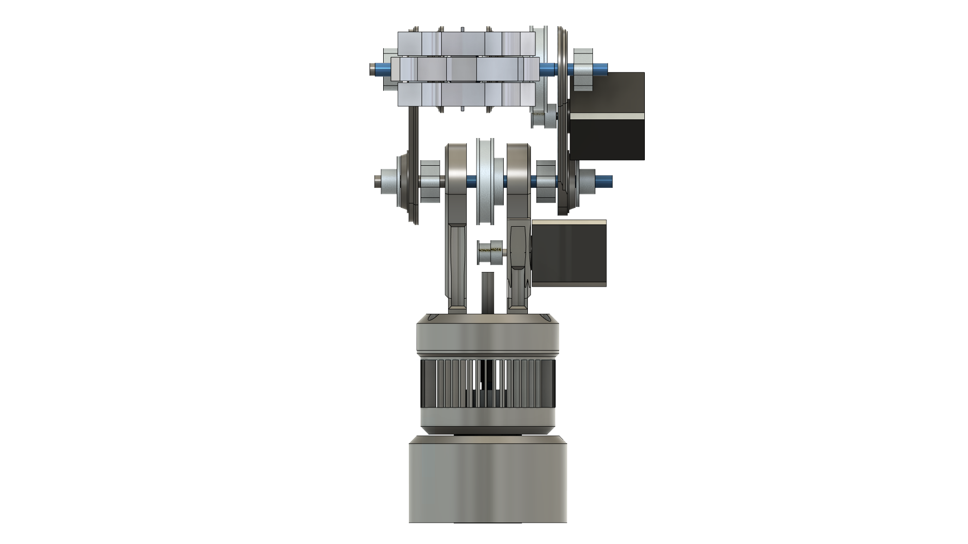
FRONT

BACK
Schematic
Purpose
The schematic shown is not a complete schematic. The schematic that is shown is used to demonstrate how the NEMA 17 stepper motor, the stepper driver, Arduino Uno, and the power supply are connected together. The other two stepper motors are connected in the same fashion, except that the motor driver's "PUL" pin and "DIR" pin are connected to different digital pins on the Arduino Uno.

Demo Video
Testing the 3-axis robotic arm for movement. A Python GUI program is used to control the movement of the 3 stepper motors
Extra Pictures

Overview of Motor Drivers, Circuit Board, Arduino, and the Robotic Arm


Overview

Component list
The project features the following components:
Rod shaft 8mm bore (4)
GT2 Timing Belt 200mm Width 6mm (3)
GT2 Pulley 20 Teeth 5mm bore 6mm Width 20T Timing Belt Pulley Wheel (3)
GT2 80 Teeth Bore 8mm Timing Pulley Wheel 6mm Width (3)
Flange coupler 8mm (5)
Mounted flange block bearing 8mm (8)
Mechanical claw end effector (1)
Short Body Nema 17 Bipolar Stepper Motor (2)
Nema 17 Stepper Motor (1)
Digital Stepper Driver (3)